Headboard Lights
Bed-area lighting. Power, brightness, and color temperature can be controlled from in the bed.

Concept
The Problem
My wife has noticed a phenomenon in her time living with me. Apparently the lighting in our apartment, coupled with our usual designated sitting and laying spots, causes me to usually be backlit from her perspective. Either I have a halo of light around me, or there's a lamp right next to my head making her have to squint at me. I kind of laughed it off at first, but it keeps coming up, so I kept it in the back of my mind for later ideas.
Ideas
For our wedding (ok, partly for our wedding) we bought 5 meters of addressable RGB LED lights for decoration. In order to make the lights less glaring, I had to severely reduce the brightness (down to something like 5% of their potential value). Thinking about that later, it seemed to me that at full brightness, those things might be strong enough to light up a room, at least to bedtime standards.
As the lights are quite pricy, I found a type for about half the price that are not individually addressable. An Arduino seemed right for the job, and looking at LED driver circuits, it seemed a pretty simple matter of a few transistors and a couple of potentiometers for controls.
Development
Controls
I wanted to control three things in this project: LED power, LED brightness, and LED hue (on a homemade color-temperature-like scale). That basically meant a pushbutton and two potentiometers. While trying to decide what sort of pots I wanted to use (slide? touch? dial?), I ran across a thumb joystick that could perform all three functions at once. Score!


Learn from my fail, though... if you use this, you'll want to grab the breakout board, too, as the pins don't follow any sort of standard. Obviously disregard if you can etch and drill your own PCBs. I'm not quite there yet.
Color Spectrum
Color Temperature Mode
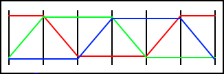
After a little web searching, I decided to make my hue progress from blue to white to yellow to red. In RGB terms, it could be charted thus:
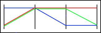
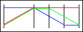
After I got everything set up, it seemed to go through a little bit of a greenish tint between white and yellow, so I brought green down to mid level in that span, making it end up more of an orange than yellow. Consequently, I also shortened the last span:
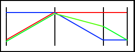
I still wasn't totally in love with this progression... it went through a weird salmon phase on its way to orange, and in fact never really went through any sort of simple warm yellow. I took a third crack at it by holding off on the drop in green for a little longer:
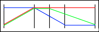
This one was a lot nicer, but after a while the wife pointed out that the prettiest orange colors occupy a fairly narrow part of the spectrum, and asked that it be lengthened to provide for a nicer sunset. Therefore, I basically doubled the length of the last zone and came up with this:
Hue Mode
In the second revision of the code, I added a Hue mode to allow use of the entire RGB spectrum. It is modeled on the hue values used in the HSL (or HSV) color space:
Brightness
Since our eyes' response to brightness is not linear, I used a gamma correction table in my code to try to compensate. The formula I used was pulled from a thread on the Microchip forums. I adapted it to a Python script (without the fancy formatting):
arraysize = 256
steps = 255
gamma = 0.6

for i in range(0, arraysize):
    dcyval = int(steps ** (((float(i)+1)/arraysize) ** gamma)+0.3)
    print str(dcyval) + ',',
The table itself can be found in the code.
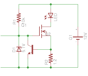
LED Driver
To perform the task of driving the LEDs, I turned to an Instructable. Consulting the LED strip's datasheet, for the length I'm using I need to provide 320mA per channel. As such, I chose a 1.2 ohm sensing resistor. The schematic for each channel (where the controlling PWM signal is coming in from the left) is:
Final Assembly
For initial prototyping, I used my Arduino Uno and a breadboard. When I had it pretty well worked out, I moved the microprocessor to the breadboard for the final testing and debugging. For the final assembly, I was just able to squeeze all the components onto one of the nice little Radio Shack PCBs. It took a little creative assembly, and a few holes drilled for the power barrel connector, but it came together nicely.


Here's a demo of the final product before installation:
Installation
The final step was installing the pieces on the back of the bed. The lights themselves come with an adhesive strip already affixed to the back, so they're easy. For the joystick, I wanted to get it someplace we could both reach, but where we can't accidentally nudge it. The ideal spot was on the back of the center beam of the bed, but there's just not enough clearance back there unless I somehow dig out a big hole that the whole thing, breakout board and all, could fit into. I'm not nearly handy enough at carpentry to know where to even begin with that, so I settled for putting it on the side of the center beam, down below the top of the mattress. The last piece was then the main board.

I wanted to put the board totally out of the way, below the joystick, but that would have required wiring up extensions for the LED strip cables. Frankly, I was ready to just get this thing done with, so I mounted it in the only spot where the strips and the joystick would already reach. It introduces a possibility that the cats could get their teeth on some of the wires, so I'll probably combat that with some bitter spray. It's also slightly visible from the front, but... yeah, like I said, I was ready to be done. It's all nice and modular, so I can always make modifications later.
Here is a video demo of the installed project. It uses version 2 of the code, which is described in the Iteration section.
Conclusion
I may have been a little bit optimistic about the brightness. While it doesn't set the room ablaze, it's enough for reading in bed (the wife agrees). The LED strips are being undervolted a little bit due to the source-drain voltage and gate-emitter voltage of the MOSFET and BJT, so something like a 13V supply might squeeze a little more brightness out.
Overall, though, I declare the project a success.
Obstacles
Low Multimeter Battery
When programming the control code, I needed to measure threshold voltages for the joystick axes. In other words, I had to set a limit beyond which the joystick would have to go in a given direction before it would start registering as a push in that direction, in order to avoid spontaneous changes happening due to the press of the button or hysteresis or any such thing. To do that, I hooked up the joystick and measured the voltage it was putting out at certain points in its travel. I then converted that to the integer value it would register in the microprocessor. It was being a little flaky, and troubleshooting (again using the multimeter) just raised more questions as I was registering much higher values than I expected in several parts of the circuit. While expressing my puzzlement, the wife asked if the multimeter was low on battery. I said "No, when it's low on battery there's a little battery icon it shows." Then, looking at the multimeter, I continued, "...erm, like that one there." A fresh 9V later, balance was restored.
Blown Microprocessor
At some point, I think I hooked the 12V supply up to the voltage into the joystick, and then fed it into the microprocessor. It wasn't happy. It was clear pretty quickly that I had blown an input, but I was able to switch to another input and continue using that chip. Unfortunately, farther down the line I had more issues with the joystick control intermittently deciding not to work on one or both axes, and after a few measurements, I could only conclude that something was still wrong with the chip. I tossed it out, flashed a fresh one, and it was fine after that.
Backwards Gamma Table
Somehow on my first attempt at a gamma table, I got the non-linearity of the formula backwards. Instead of small changes at the low end leading up to bigger changes at the high end, I was doing the opposite. It did sort of register that it still didn't look right, but at the time I just sort of made a mental note to play with it later if I had a chance. I'm glad I remembered to look at that again, because I realized my mistake pretty quickly.
Integer Types and the millis() Function
Right after installation, I started noticing that the joystick would occasionally stop registering one or both of the axes. It would be ornery like that for a while, and then start working again. I suspected this was not a fault of the hardware, so I gave the code a good hard stare. I had defaulted to declaring most of my variables as plain int, and on a hunch, I checked the description of the millis() function. Turns out it works with unsigned longs. Looking at the size of an Arduino integer, a plain int can only count about a minute's worth of milliseconds. That could definitely throw off my control delay calculations, so I switched the time variables all to unsigned long, and the issues appear to have gone away.
Iteration
Code Update (Version 2)
I substantially rewrote the Arduino code. New features were added, and I did some cleanup.
Constants and variables
I originally used variables to hold my constants, which is obviously a bit of a waste of resources on a small microprocessor. I moved them to preprocessor #define statements. While I was at it, I added a bunch more and got rid of any "magic numbers" in the code to (hopefully) help with readability.
I also switched my int variables to byte wherever possible. For the gamma table in particular that saves a significant amount of the microprocessor's limited memory.
New modes
There are now four modes of operation for the lights:
- Color Temperature (default)
- The original mode. Color spectrum is closed-ended and goes from blue to white to pale yellow to orange to red.
- Hue
- Traverses the entire RGB color spectrum (at full saturation). Cycles around.
- Sunrise
- Automatic timed mode. Uses color temperature scale. Starts with a dim red, increases it to full brightness, and shifts gradually to a warm white. Timed to approximately coincide with one cycle of my alarm clock's snooze.
- Sunset
- Automatic timed mode. Starts on a neutral white, transitions to red, and then dims to a quarter brightness. From there it sits in a sleep timer mode for a half hour, before fading away and shutting itself off.
Holding the button down for a second puts the lights in select mode (which is a sort of psychedelic rapid cycling through the Hue spectrum at quarter brightness), from which the user can select a mode by moving the joystick in the appropriate direction.
The lights will not respond to the joystick in Sunrise or Sunset mode, but pushing the button will turn the lights off and revert to Color Temperature mode. Once Sunset hits the sleep timer, it will respond to the joystick. If it does, the mode is cancelled and it switches to Color Temperature mode.
Analog control
I implemented finer control of the color and brightness by nudging the joystick in the appropriate direction. Holding the stick fully in one direction causes shifting at the same speed as before, but smaller motions can slow it as far as one-fifth (easily configurable) of full speed.
Enclosure
My wife wanted to make a smaller (one light strip) version of the project to send to a friend's daughter as a late birthday present. Of course, we don't want to send exposed electronics for a child's bed, so we needed some sort of enclosure. After considering a few options, we went with a small aluminum box that I had left over from some low-power ham radio projects. It's an LMB Heeger interlocking box model #139. The aluminum was thin enough to be able to punch a hole big enough for the joystick with a cheap knockout punch set from Harbor Freight. Combined with some spacers and miscellaneous hardware, it made a nice little case.

I used an Adafruit half-size Perma Proto PCB this time, which is slightly larger (and more expensive) than the Radio Shack board, and required a lot less use of jumper wires. For the light strip connector, I found a 4-conductor audio cable and jack capable of carrying up to 2A.

You may have noticed the rubber grommet around the light connector. After assembling everything without it, I quick realized that one of the conductors on the panel-mount socket was connected to the chassis. The way I assembled it, it happened to be the green channel. Though nothing else in the enclosure is actually grounded to the case, it caused the green lights to flicker on when touching the case. Thus I had to order the grommet to isolate the connector.

All in all, I'm quite happy with how it turned out. Here's a bill of materials for the enclosure, connectors, and hardware:
| Item | Part Number | Qty | Cost |
|---|---|---|---|
| Enclosure | LMB Heeger #139 | 1 | $10.29 |
| Power barrel connector (panel mount) | Digikey CP-5-ND | 1 | $2.43 |
| 4-conductor audio connector (panel mount) | Digikey CP5-43502PM-ND | 1 | $2.73 |
| 6' 4-conductor audio cable | Digikey CP-354S-ND | 1 | $5.08 |
| 1/4" #6 nylon spacers | Digikey 492-1104-ND | 8 | $0.39 |
| 1/8" #6 nylon spacers | Digikey 492-1102-ND | 6 | $0.29 |
| 1" 4-40 machine screws (Dremeled down to about 7/8") | Lowe's | 4 | $0.79 |
| 3/8" 4-40 machine screws | Digikey H781-ND | 2 | $0.05 |
| 4-40 lock washers | Digikey H236-ND | 6 | $0.08 |
| 4-40 nuts | Digikey H216-ND | 6 | $0.09 |
| Rubber grommet (1/4" inner diameter) | Digikey 738K-ND | 1 | $0.40 |
| Total Cost (enclosure and hardware only) | $22.62 | ||
Code Update (Version 3)
The nice enclosure presented a new problem: which way is up? I didn't want to make the end user be constrained by having to orient the box in a particular way, so I updated the code to add an extra function. If the button is held down for five seconds, the lights go from the Select Mode color shift to a rapid pulsating white. The next direction in which the joystick is pushed will be considered "up" henceforth. In order to get the setting to persist after power is removed from the device, I had to learn how to use the EEPROM of the Arduino devices, which, as it turns out, is remarkably easy.
In addition, I added a tweak to the color temperature spectrum to elongate the orange part of the progression, and changed sunset mode to start at neutral white rather than cool white, which proved to be a bit glaring.
Bill of Materials
Parts
| Item | Part Number | Qty | Cost | |
|---|---|---|---|---|
| LED1-3 | LED light strip | Sparkfun 10261 | 2 | $31.90 |
| G1 | 12V 2A AC power adapter | Mouser 552-PSA-24A-120-R | 1 | $16.96 |
| G1 | Matching barrel connector | Mouser 163-179PH-EX | 1 | $1.04 |
| IC2 | 5V DC-DC converter (could just use an LM7805) | Mouser 919-R-78E5.0-0.5 | 1 | $3.55 |
| IC1 | Atmel Atmega328P microprocessor | Sparkfun 9061 | 1 | $4.30 |
| IC1 | 28-pin DIP socket | Sparkfun 7942 | 1 | $0.86 |
| Q1 | 16MHz crystal | Sparkfun 536 | 1 | $0.95 |
| C1-2 | 22pF capacitor | Sparkfun 8571 | 2 | $0.46 |
| S1,R1-2 | Thumb joystick controller | Sparkfun 9032 | 1 | $3.95 |
| S1,R1-2 | Thumb joystick breakout board | Sparkfun 9110 | 1 | $1.95 |
| R4,6,8 | 10kΩ 1/8W resistor | Mouser 299-10K-RC | 3 | $0.18 |
| R3,5,7 | 1.2Ω 2W resistor | Mouser 594-5083NW1R200J | 3 | $0.30 |
| D1-3 | 5.1V zener diode | Mouser 512-1N5231CTR | 3 | $0.12 |
| Q2,4,6 | N-channel power MOSFET | Mouser 512-FQP50N06L | 3 | $4.17 |
| Q3,5,7 | NPN BJT | Mouser 512-2N5088BU | 3 | $0.27 |
| Printed circuit board | RadioShack 276-150 | 1 | $2.49 | |
| Male through-hole headers | Sparkfun 116 | 1 | $1.50 | |
| Female 4-pin headers | Digikey A28360-ND | 2 | $0.66 | |
| Female 6-pin header | Digikey A28367-ND | 1 | $0.68 | |
| Solder/crimp-type female header pins | Digikey A32512-ND | 13 | $1.19 | |
| Total Cost (excl. solder, hookup wire, heat shrink, etc.) | $77.48 | |||
Pricing note: The costs given are from where I happened to purchase them, and at the quantity I purchased them at. Some of these parts I've had sitting around from other projects. You can shave a few dollars off by buying more sensibly.
Required tools and supplies: Soldering iron and associated supplies, Arduino, installation hardware. If you don't have a programmer capable of loading the Arduino bootloader onto the Atmega (I use an Arduino Uno with the Adafruit programming shield), you'll need to purchase the version that comes with it already loaded.
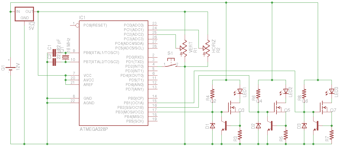
Schematic
Arduino Code
/* Include EEPROM library */
#include <EEPROM.h>

/* EEPROM locations */
#define EE_ORIENT 0

/* Orientations */
#define O_NORTH 0
#define O_WEST 1
#define O_SOUTH 2
#define O_EAST 3

/* Orientation directionality */
#define O_NORM 1
#define O_FLIP -1

/* RBG output pins */
#define PIN_R 11
#define PIN_G 10
#define PIN_B 9

/* Input pins */
#define PIN_VERT 2
#define PIN_HORIZ 1
#define PIN_POWER 2

/* Brightness and color control limit values (derived experimentally) */
#define V_UP_MIN 562
#define V_UP_MAX 984
#define V_DOWN_MIN 460
#define V_DOWN_MAX 40
#define H_UP_MIN 562
#define H_UP_MAX 984
#define H_DOWN_MIN 460
#define H_DOWN_MAX 40

/* Min and max values of color temperature and hue scales */
#define MIN_COLOR_TEMP -255
#define MAX_COLOR_TEMP 511
#define MIN_COLOR_HUE 0
#define MAX_COLOR_HUE 1535

/* Color temperature scale key values */
#define TEMP_BLUE -255
#define TEMP_COOL_WHITE -127
#define TEMP_WHITE 0
#define TEMP_WARM_WHITE 127
#define TEMP_YELLOW 191
#define TEMP_ORANGE 255
#define TEMP_RED 511

/* Hue scale key values */
#define HUE_RED 0
#define HUE_YELLOW 256
#define HUE_GREEN 512
#define HUE_CYAN 768
#define HUE_BLUE 1024
#define HUE_MAGENTA 1280

/* Brightness scale key values */
#define MIN_BRIGHT 0
#define QUARTER_BRIGHT 63
#define HALF_BRIGHT 127
#define MAX_BRIGHT 255

/* Modes */
#define MODE_TEMP 0          /* Color Temperature scale */
#define MODE_SUNRISE 1       /* Sunrise */
#define MODE_SUNSET 2        /* Sunset */
#define MODE_SUNSET_SLEEP 3  /* Sleep after sunset */
#define MODE_HUE 4           /* Hue scale */
#define MODE_SELECT 5        /* Select mode */
#define MODE_ORIENT 6        /* Orientation mode */

/* Button/debounce states */
#define STATE_NORMAL 0
#define STATE_PRESS_DB 1
#define STATE_PRESS_HOLD 2
#define STATE_RELEASE_DB 3

/* Debounce delay */
#define DB_DELAY 5

/* Power mask states */
#define P_ON 255
#define P_OFF 0

/* Control/delay step lengths */
#define SR_STEP_LENGTH 1000
#define SS_STEP_LENGTH 938
#define SS_SLEEP_STEP_LENGTH 500
#define BRIGHTNESS_STEP_LENGTH 17
#define TEMP_STEP_LENGTH 9
#define HUE_STEP_LENGTH 9
#define SELECT_STEP_LENGTH 2
#define ORIENT_STEP_LENGTH 4

/* Ratio of fastest to slowest control change speeds */
#define SPEED_RATIO 5

/* Delay before sunset mode fades to off */
#define SUNSET_SLEEP_DELAY 1800000

/* Length of longer button presses */
#define LONG_DELAY 1000
#define LONG_LONG_DELAY 5000

/* Orientation */
byte orient;

/* General state */
byte brightness;
int color;
byte mode;

/* State for power button */
byte pstate;
unsigned long ptime;

/* State for brightness control */
unsigned long btime;
int pinvalb;
byte bstepcount;

/* State for color control */
unsigned long ctime;
int pinvalc;
byte cstepcount;

/* Mode time */
unsigned long mtime;

/* Sleep time */
unsigned long stime;

/* Power mask */
byte pmask;

/* Current time (millis() function) */
unsigned long m;

/* Gamma correction table */
byte gamma[256] = {1, 1, 1, 1, 1, 2, 2, 2, 2, 2, 2, 2, 2, 2, 3, 3, 3, 3, 3, 3,
                  3, 3, 3, 4, 4, 4, 4, 4, 4, 4, 5, 5, 5, 5, 5, 5, 5, 6, 6, 6,
                  6, 6, 6, 7, 7, 7, 7, 7, 8, 8, 8, 8, 8, 9, 9, 9, 9, 10, 10,
                  10, 10, 10, 11, 11, 11, 11, 12, 12, 12, 13, 13, 13, 13, 14,
                  14, 14, 15, 15, 15, 16, 16, 16, 17, 17, 17, 18, 18, 18, 19,
                  19, 19, 20, 20, 21, 21, 21, 22, 22, 23, 23, 24, 24, 25, 25,
                  25, 26, 26, 27, 27, 28, 28, 29, 30, 30, 31, 31, 32, 32, 33,
                  33, 34, 35, 35, 36, 37, 37, 38, 39, 39, 40, 41, 41, 42, 43,
                  43, 44, 45, 46, 46, 47, 48, 49, 50, 50, 51, 52, 53, 54, 55,
                  56, 56, 57, 58, 59, 60, 61, 62, 63, 64, 65, 66, 67, 68, 69,
                  70, 72, 73, 74, 75, 76, 77, 78, 80, 81, 82, 83, 85, 86, 87,
                  89, 90, 91, 93, 94, 95, 97, 98, 100, 101, 103, 104, 106, 107,
                  109, 110, 112, 114, 115, 117, 119, 120, 122, 124, 126, 128,
                  129, 131, 133, 135, 137, 139, 141, 143, 145, 147, 149, 151,
                  153, 155, 157, 160, 162, 164, 166, 169, 171, 173, 176, 178,
                  180, 183, 185, 188, 190, 193, 196, 198, 201, 204, 206, 209,
                  212, 215, 218, 221, 224, 226, 229, 233, 236, 239, 242, 245,
                  248, 252, 255};

/* Short press of button */
void short_press() {
  /* Cancel special modes */
  if( (mode == MODE_SUNRISE) || (mode == MODE_SUNSET) || (mode == MODE_SUNSET_SLEEP) || (mode == MODE_ORIENT) ) {
    int c = color;
    int b = brightness;
    start_temp();
    color = c;
    brightness = b;
  } else if( mode == MODE_SELECT ) {
    int c = color;
    int b = brightness;
    start_hue();
    color = c;
    brightness = b;
  }
  /* Toggle pmask */
  pmask = ~pmask;
}

/* Long press of button */
void long_press() {
  /* Start select mode if not already in it */
  if( mode != MODE_SELECT ) {
    start_select();
  }
}

/* Extra long press of button */
void long_long_press() {
  /* Start orientation mode if not already in it */
  if( mode != MODE_ORIENT ) {
    start_orient();
  }
}

/* Read brightness axis of joystick */
int read_brightness() {
  /* Set proper axis and direction */
  byte pin = PIN_VERT;
  int upmax = V_UP_MAX;
  int upmin = V_UP_MIN;
  int dnmax = V_DOWN_MAX;
  int dnmin = V_DOWN_MIN;
  int dir = O_NORM;
  if( (orient == O_EAST) || (orient == O_WEST) ) {
    pin = PIN_HORIZ;
    upmax = H_UP_MAX;
    upmin = H_UP_MIN;
    dnmax = H_DOWN_MAX;
    dnmin = H_DOWN_MIN;
  }
  if( (orient == O_SOUTH) || (orient == O_EAST) ) {
    dir = O_FLIP;
  }
  /* Read pin and calculate return value */
  int val = analogRead(pin);
  int ret = 0;
  if( val > upmax ) {
    ret = SPEED_RATIO;
  } else if( val < dnmax ) {
    ret = -1 * SPEED_RATIO;
  } else if( val >= upmin ) {
    ret = (SPEED_RATIO - 1) * (val - upmin) / (upmax - upmin) + 1;
  } else if( val <= dnmin ) {
    ret = -1 * ((SPEED_RATIO - 1) * (dnmin - val) / (dnmin - dnmax) + 1);
  }
  return ret * dir;
}

/* Read color axis of joystick */
int read_color() {
  /* Set proper axis and direction */
  byte pin = PIN_HORIZ;
  int upmax = H_UP_MAX;
  int upmin = H_UP_MIN;
  int dnmax = H_DOWN_MAX;
  int dnmin = H_DOWN_MIN;
  int dir = O_NORM;
  if( (orient == O_EAST) || (orient == O_WEST) ) {
    pin = PIN_VERT;
    upmax = V_UP_MAX;
    upmin = V_UP_MIN;
    dnmax = V_DOWN_MAX;
    dnmin = V_DOWN_MIN;
  }
  if( (orient == O_SOUTH) || (orient == O_WEST) ) {
    dir = O_FLIP;
  }
  /* Read pin and calculate return value */
  int val = analogRead(pin);
  int ret = 0;
  if( val > upmax ) {
    ret = SPEED_RATIO;
  } else if( val < dnmax ) {
    ret = -1 * SPEED_RATIO;
  } else if( val >= upmin ) {
    ret = (SPEED_RATIO - 1) * (val - upmin) / (upmax - upmin) + 1;
  } else if( val <= dnmin ) {
    ret = -1 * ((SPEED_RATIO - 1) * (dnmin - val) / (dnmin - dnmax) + 1);
  }
  return ret * dir;
}

/* Set lights (color temperature scale) */
void output_temp() {
  byte br = gamma[brightness] & pmask;
  if( color < TEMP_WHITE ) {
    analogWrite(PIN_R, (color-TEMP_BLUE) * br / MAX_BRIGHT);
    analogWrite(PIN_G, (color-TEMP_BLUE) * br / MAX_BRIGHT);
    analogWrite(PIN_B, br);
  } else if( color <= TEMP_WARM_WHITE ) {
    analogWrite(PIN_R, br);
    analogWrite(PIN_G, br);
    analogWrite(PIN_B, (TEMP_ORANGE-color) * br / MAX_BRIGHT);
  } else if( color <= TEMP_ORANGE ) {
    analogWrite(PIN_R, br);
    analogWrite(PIN_G, (TEMP_RED-color) * 2 / 3 * br / MAX_BRIGHT);
    analogWrite(PIN_B, (TEMP_ORANGE-color) * br / MAX_BRIGHT);
  } else {
    analogWrite(PIN_R, br);
    analogWrite(PIN_G, (TEMP_RED-color) * 2 / 3 * br / MAX_BRIGHT);
    analogWrite(PIN_B, MIN_BRIGHT);
  }
}

/* Set lights (hue scale) */
void output_hue() {
  byte br = gamma[brightness] & pmask;
  if( color < HUE_YELLOW ) {
    analogWrite(PIN_R, br);
    analogWrite(PIN_G, color * br / MAX_BRIGHT);
    analogWrite(PIN_B, MIN_BRIGHT);
  } else if( color < HUE_GREEN ) {
    analogWrite(PIN_R, (HUE_GREEN-color) * br / MAX_BRIGHT);
    analogWrite(PIN_G, br);
    analogWrite(PIN_B, MIN_BRIGHT);
  } else if( color < HUE_CYAN ) {
    analogWrite(PIN_R, MIN_BRIGHT);
    analogWrite(PIN_G, br);
    analogWrite(PIN_B, (color-HUE_GREEN) * br / MAX_BRIGHT);
  } else if( color < HUE_BLUE ) {
    analogWrite(PIN_R, MIN_BRIGHT);
    analogWrite(PIN_G, (HUE_BLUE-color) * br / MAX_BRIGHT);
    analogWrite(PIN_B, br);
  } else if( color < HUE_MAGENTA ) {
    analogWrite(PIN_R, (color-HUE_BLUE) * br / MAX_BRIGHT);
    analogWrite(PIN_G, MIN_BRIGHT);
    analogWrite(PIN_B, br);
  } else {
    analogWrite(PIN_R, br);
    analogWrite(PIN_G, MIN_BRIGHT);
    analogWrite(PIN_B, (MAX_COLOR_HUE-color) * br / MAX_BRIGHT);
  }
}

/* Initialize sunrise mode */
void start_sunrise() {
  mode = MODE_SUNRISE;
  mtime = m;
  brightness = QUARTER_BRIGHT;
  color = TEMP_RED;
}

/* Sunrise mode */
void step_sunrise() {
  if( (m - mtime) >= SR_STEP_LENGTH ) {
    mtime = m;
    if( brightness < MAX_BRIGHT ) {  /* First increase brightness to full... */
      brightness++;
    } else {                         /* ...then move toward cooler colors... */
      color--;
    }
  }
  if( color == TEMP_YELLOW ) {       /* ...and stop at yellowish */
    mode = MODE_TEMP;
  }
  output_temp();
}

/* Initialize sunset sleep mode */
void start_sunset_sleep() {
  mode = MODE_SUNSET_SLEEP;
  mtime = m;
  stime = m;
}

/* Sunset sleep mode */
void step_sunset_sleep() {
  /* Revert to color temperature mode if joystick is operated */
  int control_b = read_brightness();
  int control_c = read_color();
  if( (control_b != 0) || (control_c != 0) ) {
    mode = MODE_TEMP;
  }
  /* Fade out after sleep delay expires */
  if( ((m - stime) >= SUNSET_SLEEP_DELAY) && ((m - mtime) >= SS_SLEEP_STEP_LENGTH) ) {
    if( --brightness == MIN_BRIGHT ) {
      /* Turn off when minimum brightness reached */
      short_press();
    }
    mtime = m;
  }
  output_temp();
}

/* Initialize sunset mode */
void start_sunset() {
  mode = MODE_SUNSET;
  mtime = m;
  brightness = MAX_BRIGHT;
  color = TEMP_WHITE;
}

/* Sunset mode */
void step_sunset() {
  if( (m - mtime) >= SS_STEP_LENGTH ) {
    mtime = m;
    if( color < MAX_COLOR_TEMP ) {         /* First move across the range to red... */
      color++;
    } else {                               /* ...then reduce brightness... */
      brightness--;
    }
  }
  if( brightness == QUARTER_BRIGHT ) {     /* ...and at quarter brightness, go into sleep delay */
    start_sunset_sleep();
  }
  output_temp();
}

/* Brightness adjust (for plain color temp and hue modes) */
void bright_adjust() {
  /* Temporary variable for step count */
  if( (m - btime) >= BRIGHTNESS_STEP_LENGTH ) {
    int control = read_brightness();
    if( (control > 0) && (brightness < MAX_BRIGHT) ) {
      bstepcount += control;
      if( bstepcount >= SPEED_RATIO ) {
        brightness++;
        bstepcount -= SPEED_RATIO;
      }
      btime = m;
    } else if( (control < 0) && (brightness > MIN_BRIGHT) ) {
      /* Calculate how fast to move */
      bstepcount += control;
      if( bstepcount >= SPEED_RATIO ) {
        brightness--;
        bstepcount -= SPEED_RATIO;
      }
      btime = m;
    }
  }
}

/* Initialize color temperature mode */
void start_temp() {
  mode = MODE_TEMP;
  btime = m;
  ctime = m;
  brightness = HALF_BRIGHT;
  color = TEMP_WHITE;
  bstepcount = 0;
  cstepcount = 0;
}

/* Color temperature mode */
void step_temp() {
  /* Make adjustments if on */
  if( pmask == P_ON ) {
    /* Adjust brightness */
    bright_adjust();

    /* Adjust color */
    if( (m - ctime) >= TEMP_STEP_LENGTH ) {
      int control = read_color();
      if( (control > 0) && (color < MAX_COLOR_TEMP) ) {
        cstepcount += control;
        if( cstepcount >= SPEED_RATIO ) {
          color++;
          cstepcount -= SPEED_RATIO;
        }
        ctime = m;
      } else if( (control < 0) && (color > MIN_COLOR_TEMP) ) {
        cstepcount += control;
        if( cstepcount >= SPEED_RATIO ) {
          color--;
          cstepcount -= SPEED_RATIO;
        }
        ctime = m;
      }
    }
  }

  /* Set lights */
  output_temp();
}

/* Initialize hue mode */
void start_hue() {
  mode = MODE_HUE;
  btime = m;
  ctime = m;
  brightness = HALF_BRIGHT;
  color = MIN_COLOR_HUE;
  bstepcount = 0;
  cstepcount = 0;
}

/* Hue mode */
void step_hue() {
  /* Make adjustments if on */
  if( pmask == P_ON ) {
    /* Adjust brightness */
    bright_adjust();

    /* Adjust color */
    if( (m - ctime) >= HUE_STEP_LENGTH ) {
      int control = read_color();
      if( control > 0 ) {
        cstepcount += control;
        if( cstepcount >= SPEED_RATIO ) {
          if( ++color > MAX_COLOR_HUE ) {
            color = MIN_COLOR_HUE;
          }
          cstepcount -= SPEED_RATIO;
        }
        ctime = m;
      } else if( control < 0 ) {
        cstepcount += control;
        if( cstepcount >= SPEED_RATIO ) {
          if( --color < MIN_COLOR_HUE ) {
            color = MAX_COLOR_HUE;
          }
          cstepcount -= SPEED_RATIO;
        }
        ctime = m;
      }
    }
  }

  /* Set lights */
  output_hue();
}

/* Initialize orientation mode */
void start_orient() {
  mode = MODE_ORIENT;
  pmask = P_ON;
  color = TEMP_WHITE;
  brightness = QUARTER_BRIGHT;
  mtime = m;
}

/* Orientation mode */
void step_orient() {
  /* Pulsating white indicator */
  if( (m - mtime) >= ORIENT_STEP_LENGTH ) {
    brightness++;
    if( brightness > HALF_BRIGHT ) {
      brightness = QUARTER_BRIGHT;
    }
    mtime = m;
  }

  /* Check inputs */
  int control_b = read_brightness();
  int control_c = read_color();
  int neworient = -1;
  if( control_b == SPEED_RATIO ) {
    neworient = orient;
  } else if( control_b == -1 * SPEED_RATIO ) {
    neworient = orient + 2;
  } else if( control_c == SPEED_RATIO ) {
    neworient = orient + 1;
  } else if( control_c == -1 * SPEED_RATIO ) {
    neworient = orient + 3;
  }
  if( neworient >= 0 ) {
    if( neworient > O_EAST ) {
      neworient -= 4;
    }
    orient = neworient;
    EEPROM.write(EE_ORIENT, orient);
    start_temp();
  }

  /* Set lights */
  output_temp();
}


/* Initialize select mode */
void start_select() {
  mode = MODE_SELECT;
  pmask = P_ON;
  color = HUE_RED;
  brightness = QUARTER_BRIGHT;
  mtime = m;
}

/* Select mode */
void step_select() {
  /* Rapid color change indicator */
  if( (m - mtime) >= SELECT_STEP_LENGTH ) {
    color++;
    if( color > MAX_COLOR_HUE ) {
      color = MIN_COLOR_HUE;
    }
    mtime = m;
  }

  /* Check inputs */
  int control_b = read_brightness();
  int control_c = read_color();
  if( control_c == SPEED_RATIO ) {
    start_temp();
  } else if( control_c == -1 * SPEED_RATIO ) {
    start_hue();
  } else if( control_b == SPEED_RATIO ) {
    start_sunrise();
  } else if( control_b == -1 * SPEED_RATIO ) {
    start_sunset();
  }

  /* Set lights */
  output_hue();
}

void setup() {
  /* Configure pins */
  pinMode(PIN_R, OUTPUT);
  pinMode(PIN_G, OUTPUT);
  pinMode(PIN_B, OUTPUT);
  pinMode(PIN_POWER, INPUT_PULLUP);
  /* Initialize time */
  m = millis();
  /* Go to default color temperature mode */
  start_temp();
  /* Initialize state */
  pstate = STATE_NORMAL;
  pmask = P_ON;
  /* Get orientation, reset if illegal value */
  orient = EEPROM.read(EE_ORIENT);
  if( orient > O_EAST ) {
    orient = O_NORTH;
    EEPROM.write(EE_ORIENT, O_NORTH);
  }
}

void loop() {
  /* Grab current time */
  m = millis();

  /* Power button detection and debouncing
     Debouncing is tracked via four states (value of pstate):
       STATE_NORMAL: Initial state, button not pressed, waiting
       STATE_PRESS_DB: Button press detected, waiting for debounce delay to expire
       STATE_PRESS_HOLD: Button held pressed, debounce delay expired, waiting
       STATE_RELEASE_DB: Button released, waiting for debounce delay to expire
  */
  if( digitalRead(PIN_POWER) == LOW ) {
    if( pstate == STATE_NORMAL ) {
      ptime = m;
      pstate++;
    } else if( pstate == STATE_PRESS_DB ) {
      if( (m - ptime) > DB_DELAY ) {
        pstate++;
      }
    } else if( pstate == STATE_PRESS_HOLD ) {
      if( (m - ptime) > LONG_LONG_DELAY ) {
        long_long_press();
      } else if( (m - ptime) > LONG_DELAY ) {
        long_press();
      }
    } else if( pstate == STATE_RELEASE_DB ) {
      if( (m - ptime) > DB_DELAY ) {
        pstate = STATE_NORMAL;
      }
    }
  } else {
    if( pstate == STATE_PRESS_DB ) {
      if( (m - ptime) > DB_DELAY ) {
        pstate++;
      }
    } else if( pstate == STATE_PRESS_HOLD ) {
      if( (m - ptime) <= LONG_DELAY ) {
        short_press();
      }
      ptime = m;
      pstate++;
    } else if( pstate == STATE_RELEASE_DB ) {
      if( (m - ptime) > DB_DELAY ) {
        pstate = STATE_NORMAL;
      }
    }
  }

  /* Execute appropriate mode */
  if( mode == MODE_SUNRISE ) {
    step_sunrise();
  } else if( mode == MODE_SUNSET ) {
    step_sunset();
  } else if( mode == MODE_SUNSET_SLEEP ) {
    step_sunset_sleep();
  } else if( mode == MODE_TEMP ) {
    step_temp();
  } else if( mode == MODE_HUE ) {
    step_hue();
  } else if( mode == MODE_SELECT ) {
    step_select();
  } else {
    step_orient();
  }
}
Comments
Comments can be left on the blog post for this project.